ASUS Tinker Board 2S - Debian I2C Example
Tinker Board 2 - Wiki
https://tinker-board.asus.com/forum/index.php?/topic/15253-waveshare-tinker-board-2-wiki/
I2C 速度
低速模式, 傳輸速度 100KHz.
快速模式 (Fast-mode, Fm) 傳輸速度 400KHz
高速模式 (High-speed mode, Hs-mode) 3.4MHz
https://tinker-board.asus.com/forum/index.php?/topic/15458-i2c-speed/
Tinker Board 2S預設是 40k (400KHz)
參考網頁
/i2c/dev-interface
https://www.kernel.org/doc/Documentation/i2c/dev-interface
Understanding I2C Communication in Linux
https://www.linkedin.com/pulse/understanding-i2c-communication-linux-beginners-guide-soheil-nazari
Full IOCTL Example
https://stackoverflow.com/questions/9974592/i2c-slave-ioctl-purpose
也可以使用 ASUS API Programming方式(只有使用範例, 無原始碼)
https://tinker-board.asus.com/tw/documentation/ter.html#api/
使用WiringPi C library for Debian也是一個方式
https://github.com/TinkerBoard/TinkerBoard/wiki/Tinker-Board-2-&-2S#3341-wiringpi-c-library-for-debian
Mraa library for android
https://github.com/TinkerBoard/TinkerBoard/wiki/Tinker-Board-2-&-2S#3342-mraa-library-for-android
下面這方式是用Linux內含標準 i2c_dev (ioctl)方法
1. 修改 /boot/config.txt 內容
intf:fiq_debugger=on
#intf:uart0=off
#intf:uart4=off
intf:i2c6=on /* 原始前面有個 # 要去除, 把 off 改為on */
#intf:i2c7=off
#intf:i2s0=off
#intf:spdif=off
#intf:spi1=off
#intf:spi5=off
#intf:pwm0=off
#intf:pwm1=off
#intf:pwm3a=off
#intf:test_clkout2=off
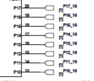
2. 把連接 I2C
SCL: pin-3
SDA: pin-5
GND: pin 5
VCC: pin 1 (3.3V)
3. 蝦皮購買的 AT24C256 EEPROM 儲存模組
https://ww1.microchip.com/downloads/en/devicedoc/doc0670.pdf
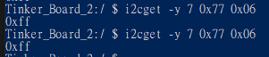
在上圖 AT24C256 EEPROM 儲存模組的 A0,A1,A2 都是 0
注意: 這顆是AT24C256
B 所以只能調整A0及A1 (A2怎調整都是0)
所以 Device Address 就是 1010000 (不含R/W) 為 0x50
在填入i2c_msg 中的addr 只要填入 0x50
i2cmsg.addr = 0x50;
那個 R/W bit 在 ioctl()的Read或Write時會自動幫忙位移及填寫
下圖是 A0 設定為 1 這樣Device Address就是 0b1010001 (0x51)
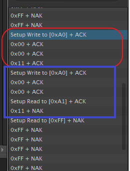
上圖是指 先送1Byte Device Address
再送 2Byte 要寫入的 EEPROM Data Address
(有些EEPROM AT24C02D是只要1個Byte的Data address, 請自行查閱規格書)
後面是實際要寫到 EEPROM 的 Data Buffer
(至於START/ACK/STOP這些旗標,在ioctl內層會幫忙回應硬體)
注意: 這個Device 單次最大64Byte, 還有這EEPROM讀寫速度並不快, 因此處理連續讀寫要慢點.
上圖是指 先送1Byte Device Address
再送 2Byte 要讀取的 EEPROM Data Address
Device會回應1Byte Device Address及要讀取 EEPROM 的 Data Buffer
但i2cmsg.buf = pI2cBuf; 只會得到後面實際EEPROM 的 Data Buffer
那Device回應的1Byte Device Address ioctl會自行處理
(至於START/ACK/STOP這些旗標,在ioctl內層會幫忙回應硬體)
下圖是AT24C02D的Page Write Command
4. 在Debian 終端機模式下
$ mkdir testi2c
$ cd testi2c
// download testi2c.c and save file
$ cc -version
$ cc -g testi2c.c -o testi2c
$ ./testi2c
5. Source Code
Write: 紅框區
Read: 藍框區
Write Command
Read Command
#include <stdio.h>
#include <stdint.h>
#include <stdlib.h>
#include <err.h>
#include <errno.h>
#include <string.h>
#include <linux/types.h>
#include <linux/i2c.h>
#include <linux/i2c-dev.h>
#include <sys/ioctl.h>
#include <sys/types.h>
#include <sys/stat.h>
#include <fcntl.h>
#include <unistd.h>
#define DEFAULT_I2C_BUS "/dev/i2c-6"
#define DEFAULT_EEPROM_ADDR 0x50 /* the 24C16 sits on i2c address 0x50 */
#define DEFAULT_NUM_PAGES 8 /* we default to a 24C16 eeprom which has 8 pages */
#define BYTES_PER_PAGE 256 /* one eeprom page is 256 byte */
#define MAX_BYTES 256 /* max number of bytes to write in one chunk */
int eeprom_write( int nFile, unsigned int nDevAddr, unsigned int nDataOffset,
unsigned char *pBuf, unsigned char nLen)
{
struct i2c_rdwr_ioctl_data msg_rdwr;
struct i2c_msg i2cmsg;
int nRecLen;
unsigned char sI2cBuf[0xFF];
unsigned char *pI2cBuf = &sI2cBuf[0];
if( nLen > MAX_BYTES)
{
fprintf(stderr,"W3-I can only write MAX_BYTES bytes at a time!\n");
return -1;
}
if( nLen + nDataOffset > 256)
{
fprintf(stderr,"W4-Sorry, len(%d)+offset(%d) > 256 (page boundary)\n", nLen, nDataOffset);
return -1;
}
msg_rdwr.msgs = &i2cmsg;
msg_rdwr.nmsgs = 1;
pI2cBuf[0] = ((unsigned char *)&nDataOffset)[1];
pI2cBuf[1] = ((unsigned char *)&nDataOffset)[0];
memcpy( pI2cBuf+2, pBuf, nLen);
i2cmsg.addr = nDevAddr;
i2cmsg.flags = 0; // Write
i2cmsg.len = 2+nLen;
i2cmsg.buf = pI2cBuf;
if( ( nRecLen = ioctl( nFile, I2C_RDWR, &msg_rdwr)) < 0)
{
perror("W5A-ioctl()");
fprintf( stderr,"W5B-ioctl %d\n%s\n", nRecLen, strerror(errno));
return -1;
}
else
{
if( pBuf != NULL)
{
fprintf( stderr,"W7-Write %d bytes to eeprom at 0x%02x, offset %08x, Data: 0x%02x\n",
nLen, nDevAddr, nDataOffset, pBuf[0]);
}
return nRecLen;
}
}
int eeprom_read( int nFile, unsigned int nDevAddr, unsigned int nDataOffset,
unsigned char *pBuf, unsigned char nLen)
{
struct i2c_rdwr_ioctl_data msg_rdwr;
struct i2c_msg i2cmsg[2];
unsigned char sAdsBuf[3];
unsigned char *pAdsBuf = &sAdsBuf[0];
int nRecLen;
if( nLen > MAX_BYTES)
{
fprintf(stderr,"R3-I can only write MAX_BYTES bytes at a time!\n");
return -1;
}
msg_rdwr.msgs = i2cmsg;
msg_rdwr.nmsgs = 2;
pAdsBuf[0] = ((unsigned char *)&nDataOffset)[1];
pAdsBuf[1] = ((unsigned char *)&nDataOffset)[0];
i2cmsg[0].addr = nDevAddr;
i2cmsg[0].flags = 0; // Write
i2cmsg[0].len = 2;
i2cmsg[0].buf = pAdsBuf;
i2cmsg[1].addr = nDevAddr;
i2cmsg[1].flags = I2C_M_RD; // read data, from slave to master
i2cmsg[1].len = nLen;
i2cmsg[1].buf = pBuf;
if( ( nRecLen = ioctl( nFile, I2C_RDWR, &msg_rdwr))<0)
{
perror("R5-eeprom_read ioctl failed");
fprintf(stderr,"R6-eeprom_read ioctl returned %d\n", nRecLen);
return -1;
}
else
{
fprintf( stderr,"R7-Read %d bytes from eeprom at 0x%02x, offset %08x, Data: 0x%02x\n",
nLen, nDevAddr, nDataOffset, pBuf[0]);
return nRecLen;
}
}
int main(void)
{
int nDevAddr = 0x50, nDataOffset, nRecLen;
int nFile, nRc, nI, nH;
int nRWTestCount = 1;
const char *pDevice = DEFAULT_I2C_BUS; //"/dev/i2c-6";
unsigned char sBuf[0xFF];
unsigned char *pBuf= &sBuf[0];
unsigned long nFuncs;
printf("Hello! This is a test prgoram.\n");
nFile = open( pDevice, O_RDWR);
if( nFile < 0)
err( errno, "O1-Tried to open '%s'", pDevice);
else
printf( "\nO2-Open dev i2c-6 success.\n");
if (ioctl( nFile, I2C_FUNCS, &nFuncs) < 0)
{
perror("W5A-ioctl()");
fprintf(stderr, "Error: Could not get the adapter functionality matrix: %s\n",
strerror(errno));
close( nFile);
exit(0);
}
ioctl( nFile, I2C_TIMEOUT,2);// TIMEOUT
ioctl( nFile, I2C_RETRIES,1);// retry count
nRc = ioctl( nFile, I2C_SLAVE, nDevAddr);
if( nRc < 0)
{
err(errno, "O3-Tried to set device address '0x%02x'", nDevAddr);
exit(0);
}
else
{
printf("O4-Dev i2c-6 Set Address 0x50 success.\n");
}
nDevAddr = 0x50;
nDataOffset = 0;
nWriteLen = 8;
nRWTestCount = 8;
for( nI = 0; nI < nRWTestCount; nI++)
{
sleep(1); // 2sec
for( nH = 0; nH < 0xFF; nH++)
pBuf[nH] = 20+nI+nH;
nDataOffset = nI*nWriteLen;
nRecLen = eeprom_write( nFile, nDevAddr, nDataOffset, pBuf, nWriteLen);
if( nRecLen < 0)
{
printf( "W3A-eeprom_write failed.\n");
exit(0);
}
else
{
fprintf( stderr, "W-%d: 0x%02x 0x%02x 0x%02x 0x%02x 0x%02x 0x%02x 0x%02x 0x%02x\n",
nDataOffset,
pBuf[0], pBuf[1], pBuf[2], pBuf[3], pBuf[4], pBuf[5], pBuf[6], pBuf[7]);
}
}
// Read Process
fprintf( stderr, "\n\nR0-eeprom_Read start...\n");
nDevAddr = 0x50;
nReadLen = 8;
for( nI = 0; nI < nRWTestCount; nI++)
{
for( nH = 0; nH < 0xFF; nH++)
sBuf[nH] = 0xFF;
sleep(1); // 2sec
nDataOffset = nI*nReadLen;
nRecLen = eeprom_read( nFile, nDevAddr, nDataOffset, pBuf, nReadLen);
if( nRecLen < 0)
{
printf("R1-eeprom_read failed. %d\n", nI);
exit(1);
}
else
{
fprintf( stderr, "R-%d: 0x%02x 0x%02x 0x%02x 0x%02x 0x%02x 0x%02x 0x%02x 0x%02x\n",
nDataOffset,
pBuf[0], pBuf[1], pBuf[2], pBuf[3], pBuf[4], pBuf[5], pBuf[6], pBuf[7]);
}
}
close( nFile);
return 0;
}